Tuesday, 25 September 2012

WEEK 9 FYP 2


Title of objective:

test the led  and lcd panel result that act as output for stage of motor.

OBJECTIVES

we can see or know the output of this project.

CONTENT/PROCEDURE

1. Connect the project with battery.
2.make sure all the connection is okay.
3. all the result is recorded.

ANALYSIS


This table and figure above is taken when we do testing. all the data i combine in table above to make it clearly to see.

Conclusion

the result is based on the testing but when doing this testing some problem come from technical or mechanical part too.

Monday, 17 September 2012

WEEK 8 FYP 2

 
Title of activity:

Combine the hardware of mechanical part with the circuit programming.

OBJECTIVES:

To make the prototype operate with the main program.

CONTENT/ PROCEDURE:

1. use the screw and screw drill.
2. make a hole at base by using screw drill.
3. screw the circuit to the base.

 ANALYSIS:


Conclusion:

it will be great if can put the circuit in upper seat but the prototype is small so it's can't. But if upgraded it can be change ;)

Monday, 10 September 2012

WEEK 7 FYP 2


Title of activity:

 Make the programming by using assembly language and pic 16F877A

OBJECTIVES:
To make sure the prototype can function by using the instruction in programming.

CONTENT/ PROCEDURE:
1. Do the programming based on process of flowchart and block diagram.


ANALYSIS:

By using this pic and the function of each pin the prototype can function very well, insyaALLAH. PIC is a family of modified Harvard architecture microcontrollers made by Microchip Technology, the name PIC initially referred to "Peripheral Interface Controller". PICs are popular with both industrial developers and hobbyists alike due to their low cost, wide availability, large user base, extensive collection of application notes, availability of low cost or free development tools, and serial programming (and re-programming with flash memory) capability. We used this pic in our circuit to control the wheelchair.


CONCLUSION:

The hardware or the mechanical part cannot function if the programming have the problem. Pic is like the main brain for this project.

Tuesday, 4 September 2012

WEEK 6 FYP 2


Title of activity:

Put the component at PCB for each circuit.

CONTENT/ PROCEDURE:

1. Make the design where to put the component and the connection.
2. using the solder to connect the component.
3. use the multimeter to check the connection.

ANALYSIS:


below is the circuit of driver motor circuit that after solder.


below is the circuit that combine with lcd panel and switch


CONCLUSION:

When doing this, must make sure the connection is okay. therefore the output can be okay.

Wednesday, 29 August 2012

WEEK 5 FYP 2


Title of activity:


Proposing the circuit for etching in PCB board. 

OBJECTIVES:

Showing the circuit for etching purpose.

CONTENT/PROCEDURE:

Here, I would like to present the circuit drawn after the schematic circuit. This is where I should print on the PCB board.

ANALYSIS:

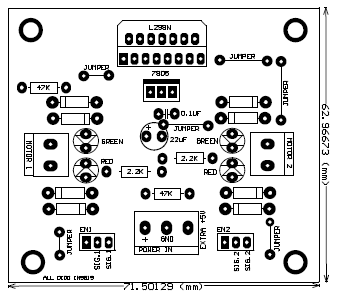
this layout for ecthing is the motor driver Circuit.


below is the pcb layout for PIC circuit for this project.

CONCLUSION:

by using this etching for PCB it is more easy to design the circuit and to solder the circuit. it ease our problem and more easy.

Wednesday, 22 August 2012

WEEK 4 FYP 2


TITLE OF ACTIVITY:

Do the hardware of this prototype.

OBJECTIVES:

To make the hardware for prototype so its can see the mechanical part of this project.

CONTENT/PROCEDURE:

1. Try to make the hardware like this picture.

2. Make the prototype by using aluminium.

3.  make the base by using of the plastic.
4. use screw to make it complete.
5. put a dc motor to make it function.


ANALYSIS:

 do you think what it will be? can you imagine my prototype?
this is my prototype after i redo many time due to mechanical problem.


CONCLUSION:

from doing this mechanical part, the design is the important thing in this part. make sure all the material, size, design is suitable and fix with objective in this project.


Wednesday, 15 August 2012

WEEK 3 FYP 2


Title of activity:


Block diagram and flow chart

Objectives:

To explain clearly about process of this project

Content/Procedure: 

1. list all the input and output.
2. State the process of the project.

ANALYSIS

 The switch is the input of this project. The users give instruction by using this switch. Then the input from the switch is fed to PIC micro controller. The pic microcontroller will control the program and give instruction to the DC motor control which is the H bridge circuit. This make the dc motor get instruction and perform the results in wheelchair which we can see the results in mechanical performance. PIC that will use in this project is PIC 16F877A that working like a brain to receive the input from the switch and give instruction to motor to operate. It also produces output to the blinking of Led and LCD’s display.

The flowchart is discussed about the whole of process of project. This project will program that this prototype will operate when get command from the user by switch. Then the command from the user is the input for pic program and will produce output which is LCD display, red and green led that act as indicator, the movement of wheel and reclining’s part.

 CONCLUSION

The blcok diagram and flow chart must correct so the flow or process this project can be smooth. InsyaAllah.